FreeRTOS Demo for the Microchip ATmega-0 Port
using the XC8, AVR-GCC and IAR EWAVR compilers
[RTOS Ports]
There are multiple FreeRTOS ports for the Microchip AVR microcontrollers – this page describes the ports for the ATmega-0 family.
Ports are available for Atmel AVR-GCC, XC8 and IAR Embedded Workbench for AVR (IAR EWAVR) compilers.
Devices supported
The demos and examples described here are configured for the ATmega4809, which has 48 KB Flash and 6 KB SRAM. The size
of the FreeRTOS demo depends on the compiler used, but in the Full Demo configuration it requires about
15 KB of program memory or less. Running 10 real-time tasks, in addition to the idle task, requires approximately 2 KB of SRAM,
so there is more than enough SRAM left for communication buffering, advanced algorithms and other SRAM intensive parts of the
application.
More information about the ATmega-0 microcontrollers can be found on the
ATmega-0 page.
Compilers and IDEs supported
Ports are available for three different compilers. The versions used to develop the ports are shown in parentheses:
- XC8 (v2.20)
- AVR-GCC (build 3.6.2.1778)
- IAR EWAVR (7.30)
The following IDE versions were used to develop and test the ports:
Microchip MPLAB X
(5.40 with device pack ATmega_DFP 2.2.108)
for the XC8 port
Atmel Studio 7
(7.0.2397 with device pack ATmega_DFP 1.4.351)
for the AVR-GCC port and the demo application projects
The XC8 and AVR-GCC compilers are integrated into the Microchip MPLAB X and the Atmel Studio 7 IDEs.
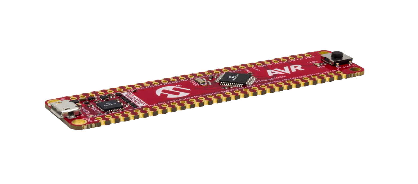
Demo applications
The FreeRTOS demo applications for the ATmega-0 microcontroller (blinky demo, minimal demo, full demo) all target the
ATmega4809 Curiosity Nano evaluation kit. The demo applications can be built with either MPLAB X (XC8), Atmel Studio
(AVR-GCC), or IAR EWAVR.
A more advanced example application is available from Atmel START. The example targets a combination of three boards: the
Curiosity
Nano Base for Click boards, the ATmega4809 Curiosity Nano evaluation kit, and the
OLED1 Xplained Pro board.
IMPORTANT! Notes on using the Microchip AVR Dx port
Please read all the following points before using this RTOS port.
- Source code organisation
- The demo application functionality
- Building and running the RTOS demo application using Microchip AVR Dx in the QEMU
emulator
- RTOS configuration and usage details
Also see the FAQ My application does not run, what could be wrong?.
Source Code Organization
The code of the FreeRTOS kernel and demos is available to download from the main download page on FreeRTOS.org.
The FreeRTOS zip file download contains the source code for all the FreeRTOS ports and demo applications – it therefore contains many more files than are needed for this project. See the Source Code Organization section for a
description of the directory structure and information on creating a new FreeRTOS project.
The MPLAB X project for the ATmega4809 demo application is in the FreeRTOS/Demo/AVR_ATMega4809_MPLAB.X directory.
The Atmel Studio 7 project for the ATmega4809 demo application is called RTOSDemo.atsln and is located in the
FreeRTOS/Demo/AVR_ ATMega4809_AtmelStudio directory.
The IAR EWAVR project for the ATmega4809 demo application is called RTOSDemo.eww and is located in the
FreeRTOS/Demo/AVR_ ATMega4809_IAR directory.
The Microchip ATmega-0 Demo Application
Functionality
Each port comes with three different demos selectable by a define (#define mainSELECTED_APPLICATION) in the
main.c file. Each demo has its own main-<demo-name>.c file. This structure is used for all
three IDEs (Atmel Studio 7, MPLAB X and IAR EWAVR). All of them use an identical FreeRTOSConfig.h file
that accommodates the most comprehensive demo (Full Demo).
Blinky Demo
If mainSELECTED_APPLICATION is set to 0 then main() calls main_blinky() that creates
a simple demo as follows:
The main_blinky() function creates one queue and two tasks, then starts the RTOS scheduler.- The Queue Send Task is implemented by
prvQueueSendTask() in main_blinky.c. It sends a fixed value
(100) to the queue every 200 milliseconds.
- The Queue Receive Task is implemented by
prvQueueReceiveTask() in main_blinky.c. It blocks on queue
reads, then unblocks and toggles an LED each time the message from the queue send task is received. The queue send task
sends to the queue every 200 milliseconds, so the queue receive task leaves the Blocked state and toggles the LED every
200 milliseconds.
Minimal Demo
If mainSELECTED_APPLICATION is set to 1, then main() calls main_minimal() that creates the
following test tasks:
- The Integer Math Test is implemented by
vStartIntegerMathTasks() in the integer.c file.
This creates a task function that repeatedly performs a 32-bit calculation and checks the result against the expected
one.
- The Register Test is implemented by
vStartRegTestTasks() in the regtest.c file. It creates
two tasks that write different values in all registers and verifies that their contents are preserved during the
context switch
- The Polled Queue Test is implemented by
vStartPolledQueueTasks() in the PollQ.c file. It
creates two tasks that communicate over a single queue. One task act as a producer, the other as a consumer, all queue
accesses being performed without blocking.
- The Serial Communication Test is implemented by
vAltStartComTestTasks() in the comtest.c file.
It creates two tasks that operate on an interrupt driven serial port. A loopback connector should be used so that
everything that is transmitted is also received.
Finally, the Check Task implemented by vErrorChecks() is created to periodically inspect the standard demo tasks
in order to ensure all the tasks are functioning as expected. The check task also toggles an LED to give visual feedback of
the system status. If the LED toggles every 3 seconds, then the check task has not discovered any problems. If the LED stops
toggling, then the check task has discovered a problem in one or more tasks.
The minimal demo project files are provided to demonstrate the use of the RTOS kernel and are not intended to provide an
optimized solution. This is particularly true for comtest.c which uses an example interrupt-driven UART
driver (serial.c), and is written with the intent of stressing (and therefore testing) the RTOS kernel
implementation rather than providing an example of an optimal solution.
Full Demo
If mainSELECTED_APPLICATION is set to 2 then main() calls main_full() to create a comprehensive
demo that demonstrates and tests many FreeRTOS features, including tasks,
direct to task notifications, queues,
semaphores, software timers, and
more. The following tests are created:
- The Semaphore test Task implemented by
vStartSemaphoreTasks() in the semtest.c file creates
two sets of two tasks each. The tasks within a set share a variable, whose access is guarded by a semaphore.
- The Direct to Task Notification Task implemented by
vStartTaskNotifyTask() in the TaskNotify.c
file creates a task that itself performs some tests. It then loops around, being notified by both a software timer and
an interrupt.
- The Register Test Task implemented by
vStartRegTestTasks() in the Regtest.c file creates two tasks
that write different values in all registers and that verify that the contents of the registers are preserved during the
context switch.
- The Recursive Mutex Task implemented by
vStartRecursiveMutexTasks() in the RecMutex.c file
demonstrates the use of recursive mutexes. It creates three tasks that all access the same recursive mutex.
Then the Check Task implemented by vErrorChecks() is created and periodically inspects the standard demo tasks
to ensure all the tasks are functioning as expected. The check task also toggles an LED to give visual feedback of the
system status. If the LED toggles every 3 seconds, then the check task has not discovered any problems. If the LED stops
toggling, then the check task has discovered a problem in one or more tasks.
The created tasks are from the set of standard demo tasks. Standard demo tasks are used by all
FreeRTOS port demo applications and have no specific functionality. They are used to demonstrate how to use the FreeRTOS API,
and to test the RTOS port.
Building the RTOS demo application
Development tools options
The demo applications are available for Atmel Studio, MPLAB X and IAR EWAVR. This implies three compilers: AVR-GCC, XC8 and
IAR EWAVR. From the demo-code point of view all three demo projects are identical. Also, the porting files are identical for
Atmel Studio and MPLAB X, but the porting files for IAR EWAVR are different.
Preparing project files
To start, first get the code for the FreeRTOS kernel and the demos by downloading (or recursively cloning) the GitHub
repository (
https://github.com/FreeRTOS/FreeRTOS). The FreeRTOS download includes source code for multiple processor ports and
demo applications, but each supported processor architecture requires a small amount of architecture-specific RTOS code. This
is the RTOS portable layer, and it is located in the FreeRTOS-Kernel/Source/Portable/<compiler>/<architecture>
sub-directories, where <compiler> and <architecture> are the compiler used to create the port, and the architecture
on which the port runs, respectively. Please see the FreeRTOS source code organization page for a
full explanation of the FreeRTOS directory structure.
Note: The port files for the GCC and XC-8 compilers are identical, so the MPLAB-X projects use porting files located in the
.../Portable/GCC/AVR_Mega0 folder.
For the ATmega-0 devices, all necessary port files and demos can be found on the following folders:

Folder Structure.
The next step is to open the application from its project folder within FreeRTOS/Demo. The projects for each
IDE/compiler already have all the necessary files linked.
Building with MPLAB X and XC8
To compile the demo project using MPLAB X follow these steps:
- Start MPLAB-X.
-
From the start menu, go to File -> Open Project and browse to the folder where the project is located:
- Select "AVR_ATMega4809_MPLAB.X" and open it.
- Build the project.
Building with Atmel Studio 7 and AVR-GCC
To compile the demo project using Atmel Studio 7, follow these steps:
- Start Atmel Studio.
-
In the tool menu, go to File -> Open -> Project/Solution. Browse to the folder where the project is located:
- Select "RTOSDemo.asln" and open the project.
- Build the project.
Building with IAR EWAVR
To compile the demo project using IAR EWAVR, follow these steps:
- Start IAR Embedded Workbench.
-
From menu, go to File -> Open Workspace and browse to the project location:
- Select "RTOSDemo.eww" and open it.
- Build the project.
Configuration and Usage Details
RTOS port specific configuration
Configuration items specific to FreeRTOS demos are in the FreeRTOSConfig.h file located in each project folder.
Below are few define examples. All constants defined in this file can be edited to suit a specific application.
#define configCPU_CLOCK_HZ - microcontroller clock, used by timers and to calculate delays and baud-rates
for communications.#define configTICK_RATE_HZ – used to set the frequency of the RTOS tick. All demos use a value of 1000Hz
to test the RTOS kernel functionality. #define configUSE_PREEMPTION - used to switch between the preemptive and cooperative FreeRTOS kernels.#define configUSE_TIMER_INSTANCE - the port allows the user to select what timer is used for the RTOS tick.
The list of available options is detailed in the FreeRTOS_Config.h file, and the support functions/macro's
are located in the porthardware.h file.
Each port also defines the type 'BaseType_t' to be equal to the most efficient data type for that processor.
The ATmega-0 ports define 'BaseType_t' as char (8 bits):
#define portBASE_TYPE char
Note: The tick timer options list contains options that are available on the larger members of the ATmega-0 family. Please
refer to the specific device datasheet for a list of available options.
Memory areas used by the compiler
The FreeRTOS port requires you to define the heap and stack used by compiler. These are defined to accommodate the more
comprehensive demo example (Full Demo), but the size is customizable and depends only on the
implementation of your application. The current port uses the following defines (these are similar for all tools/compilers):
#define configTOTAL_HEAP_SIZE 0x1000#define configMINIMAL_STACK_SIZE 120
Note: The IAR compiler requires two stacks (CSTACK and RSTACK); the CSTACK is
configured to 120 bytes and the RSTACK to 30 bytes.
Memory allocation
Source/Portable/MemMang/heap_1.c is included in the ATmega4809 demo application project to provide the memory
allocation required by the RTOS kernel. Please refer to the Memory Management section of the
API documentation for complete information.
Demo application USART and port drivers
The demos application folder contains examples for two drivers.
- The USART driver is included in the
serial.c file. It is an interrupt-based driver that uses the USART
instance connected to the onboard debugger USART. This way, the messages sent by the serial communication test task
(ComTest) can be viewed on the PC without requiring any special hardware other than the board itself
and a USB cable. The USART driver enables the internal loopback connection between the RX and TX signals because the
ComTest verifies the sent data is received back without error.
- The demo applications include a file called
partest.c that is a driver for a whole port of the MCU.
(The name is historic and has since lost its meaning but it is derived from 'parallel port test'.) The file contains
the interface functions for setting LEDs, clearing LEDs and toggling LEDs. In these examples, port C was chosen as the
port where the onboard LED is connected. The LED pin is chosen because getting the LED output working is the first step
when porting a demo from one hardware platform to another. For the selected hardware platform (ATmega4809 Curiosity
Nano), the other LED pins controlled by partest.c are not physically connected to an LED.
Other notes
It is not necessary to read this section in order to use the port.
Using an alternative hardware platform
The ATmega4809 Curiosity Nano was chosen for its easy-to-get-started features, but any other hardware platform can be used
with minimal additional effort. The multiple options available for the tick timer and the available demos facilitate the
development of FreeRTOS applications on any device in the ATmega-0 family.
Using an alternative ATmega-0 device
The FreeRTOS demo port can run on any device in this family. Simply change the device type in the development tool
configuration window and then re-compile the project. The number of tasks used, and the complexity of the application will
dictate the size of the program and of data memory, and thus indicate which device can be used.
Tick timer selection
All available demo ports use TCB0 as the default tick timer (#define configUSE_TIMER_INSTANCE 0). This timer is
available on all ATmega-0 devices. Other timers can be selected with configUSE_TIMER_INSTANCE as follows (refer
to the FreeRTOS_Config.h file for available options):
#define configUSE_TIMER_INSTANCE 0 - use TCB0 as the tick timer #define configUSE_TIMER_INSTANCE 1 - use TCB1 as the tick timer #define configUSE_TIMER_INSTANCE 2 - use TCB2 as the tick timer #define configUSE_TIMER_INSTANCE 3 - use TCB3 as the tick timer #define configUSE_TIMER_INSTANCE 4 - use RTC as the tick timer
Clock configuration
The ATmega-0 ports use an on-chip oscillator as the main clock. Because of its internal architecture, only certain
predefined values can be used for the internal clock. To ensure an easy start-up with the ATmega-0 platform, an additional
clk_config.h file is provided. This file contains a list of supported clock configurations, clock initialization
procedures (clk_init()), and uses #define configCPU_CLOCK_HZ (in file FreeRTOS_Config.h)
as input.
Serial port configuration
When mainSELECTED_APPLICATION is set to 1, the project includes an example of an interrupt-driven driver for
serial communication that uses the USART3 instance (file serial.c). Any other available USART instance (USART0-3)
can be used as a direct replacement if necessary. In addition, the USART Rx and Tx pins should be configured. For the current demo
this is done in the hardware initialization procedure:
void init_minimal( void )
{
    /* Configure UART pins: PB1 Rx, PB0 Tx */
    PORTC.DIR &= ~PIN0_bm;
    PORTC.DIR |= PIN1_bm;

    ...
}
LED port configuration
LEDs provide the easiest method of getting visual feedback that the demo application is running, so it is useful to get
the LEDs on the new hardware platform working as soon as possible.
It is unlikely that the hardware platform to which the demo is ported has LEDs on the same IO ports as the hardware
platform on which the demo was developed – so some minor modifications will be required.
The function vParTestInitialise() in the partest.c file contains the IO port mode and direction
configuration. The function prvSetupHardware() in main.c contains additional generic hardware
configurations and may also require some modifications, depending on the port being used.
Make any changes necessary to the two functions referred to in the paragraph above, then write a very simple program to
check that the LED outputs are working.
Using interrupts
The interrupts that are not used for context switching can be used without special requirements. The method used to install
the interrupt vectors depends on the port and compiler used. Refer to the existing demo for the port you are using. If an
interrupt is used for the context switch, it requires special handling. Refer to serial.c and the porting files
for examples of using interrupts for the context switch.
Copyright (C) Amazon Web Services, Inc. or its affiliates. All rights reserved.